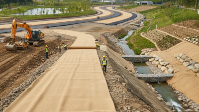
How to Choose the Right Nonwoven Geotextile Fabric

Choosing nonwoven geotextile fabric starts with the soil, water flow, and installation conditions beneath your project. A drainage trench in silty ground needs different filtration properties than a gravel access road carrying repeated truck loads. Weight alone is insufficient. A heavier roll may look reassuring, yet it can still provide unsuitable filtration or inadequate resistance to installation damage. The practical question is whether the fabric can retain soil while allowing water to pass under expected site conditions.

The Federal Highway Administration’s Geosynthetics Engineering report, FHWA NHI-07-092 (2008), explains how filtration, drainage, separation, and stabilization require different design considerations. Its guidance supports evaluating soil compatibility and hydraulic performance instead of selecting material solely by mass per unit area. Check the test methods. ASTM D4751 measures apparent opening size, while ASTM D4491 evaluates water permeability through geotextiles using permittivity. ASTM D6241 measures static puncture strength, providing another useful comparison when reviewing technical data sheets for fabrics exposed to aggregate placement. These measurements describe different properties; none independently establishes that a product suits your site.

This guide explains how to compare those properties alongside soil gradation, aggregate size, drainage requirements, and construction methods. For example, angular stone dropped during backfilling creates installation demands that a neatly prepared laboratory specimen does not fully represent. There is an uncomfortable limitation: a complete-looking specification can still overlook variable ground conditions. Manufacturer data provide a starting point. Reliable selection also requires representative soil information and, where conditions warrant, engineering review of filtration compatibility and installation survivability.

How to Choose the Right Nonwoven Geotextile Fabric

Understand Nonwoven Geotextile Fabric Types and Functions

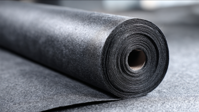
Nonwoven geotextile fabric separates soil layers while allowing water to pass through its connected pores. Its manufacturing method affects how it performs. Needle-punched fabrics have mechanically entangled fibers, creating a felt-like structure commonly used for filtration, drainage, and cushioning. Heat-bonded fabrics use thermal bonding and often have a thinner, smoother structure. Neither type suits every project. For example, beneath a gravel walkway, separation helps prevent soft soil from mixing into the stone. Beside a perforated drainpipe, filtration helps retain soil while water enters the drainage aggregate.

Match the fabric to the soil and installation conditions, rather than choosing by thickness alone. Check the details. Apparent opening size helps assess soil retention, while permittivity indicates water flow through the fabric under test conditions. Puncture resistance matters when angular stone presses against the material during installation. For pond liners, cushioning performance deserves particular attention because sharp stones can create concentrated pressure. Heavier can feel safer. I would question that instinct: additional weight alone does not establish suitable filtration or protection. Fine silts and difficult drainage conditions may require soil-specific testing and professional design advice.

Tips: Request a technical datasheet with test methods, not just a roll weight. Compare opening size, permittivity, and puncture resistance against project requirements. Before covering the fabric, remove sharp debris and check seams, overlaps, and wrinkles against installation specifications. Dumping aggregate directly onto exposed fabric can damage it.
Define Your Project’s Soil Conditions and Performance Needs

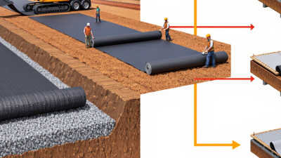
Choosing nonwoven geotextile starts with the soil touching it. Record grain size, groundwater levels, and whether excavation exposes soft clay, silty sand, or angular gravel. Test the fines. A sieve analysis measures particles passing the 0.075 mm sieve, a key input for filtration design. Also document seasonal seepage and expected wheel loads. A muddy trench after rainfall provides useful evidence, but it cannot replace laboratory soil classification.

For subsurface drainage, AASHTO M 288 specifies minimum permittivity according to the percentage passing that sieve. Its baseline values are 0.5, 0.2, and 0.1 s⁻¹ for soils containing <15%, 15–50%, and >50% fines, respectively. Permittivity describes water flow through the fabric under a hydraulic head difference. Check retention too. Apparent opening size, measured using ASTM D4751, helps assess whether soil particles could migrate through the fabric. These specification values support screening; unusual soils may require project-specific filtration testing.

Define what failure would look like on your site. Beneath an access road, rutting and aggregate mixing may make separation and installation survivability priorities. Around a perforated drain, soil retention and sustained water flow become central. Heavier fabric can seem reassuring, but mass alone does not establish suitability. That shortcut deserves scrutiny, especially when angular stone will be dropped directly onto exposed fabric. Specify puncture resistance, placement conditions, and acceptance criteria before comparing products.

How to Choose the Right Nonwoven Geotextile Fabric: Define Your Project’s Soil Conditions and Performance Needs

Start with your soil’s particle-size distribution. The chart shows the particle-size boundaries used in the USDA soil classification system. These reference values help explain soil texture; they are not recommended geotextile opening sizes.

USDA particle-size ranges: sand, 0.05–2 mm; silt, 0.002–0.05 mm; clay, below 0.002 mm.

Reading the chart: Each bar marks the upper size boundary of a particle class. Sand spans 0.05–2 mm, silt spans 0.002–0.05 mm, and clay particles are smaller than 0.002 mm. The vertical axis is logarithmic, so equal spacing represents equal size ratios rather than equal differences.

Match filtration and drainage to the soil. Use a sieve analysis and, where needed, a sedimentation analysis to establish the full gradation. Select an apparent opening size that retains the soil while allowing water to pass, and check cross-plane water flow capacity against the expected drainage demand. Fine-grained soils may require soil–geotextile compatibility testing to assess clogging potential.

Check installation and service demands. Consider aggregate size, placement methods, construction traffic, subgrade strength, and hydraulic conditions. Specify appropriate puncture resistance and other strength requirements alongside filtration properties. Relevant test methods include ASTM D4751 for apparent opening size, ASTM D4491/D4491M for water permeability by permittivity, and ASTM D6241 for static puncture strength.

Data source: USDA NRCS Soil Survey Manual, soil particle-size classification. Particle-size boundaries alone are insufficient to specify a geotextile; final requirements depend on site conditions and engineering design.

Compare Filtration, Drainage, Strength, and Durability Properties

Choosing nonwoven geotextile starts with the soil, not the fabric’s weight. For filtration, compare apparent opening size with the soil’s particle distribution and expected flow conditions. Openings must retain soil while allowing water through. Check compatibility. A fabric that works beneath coarse gravel may clog against silty soil. For drainage, review permittivity, which describes water flow through the fabric under specified test conditions. High laboratory flow values alone cannot predict performance after soil contact and installation.

Strength matters most when aggregate placement, compaction, or uneven ground could damage the fabric. Compare puncture resistance and tensile properties using results from matching test methods. Angular stone dropped directly onto exposed fabric creates different demands than carefully placed rounded gravel. Installation matters. A heavier product may offer greater protection, but weight alone does not establish adequate strength. Request project-relevant test data, including puncture results measured under ASTM D6241 where that method applies.

Durability depends on exposure, soil chemistry, and the expected service life. Check ultraviolet resistance when rolls might remain uncovered during construction. Also confirm compatibility with site pH and any unusual chemical exposure. For drainage within the fabric’s plane, evaluate transmissivity under representative loads. Compression can reduce that capacity. Choosing the thickest material feels reassuring, yet that instinct deserves scrutiny when hydraulic performance controls the design.

How to Choose the Right Nonwoven Geotextile Fabric - Compare Filtration, Drainage, Strength, and Durability Properties

Compare measurable engineering properties to select a fabric that retains soil, passes water, and survives installation and service conditions.

Selection criteria for nonwoven geotextiles. Numerical examples below are unit conversions, not product performance claims or universal acceptance limits.
Selection Area Property and Units Relevant Test Method How to Interpret the Data Selection Guidance and Tradeoffs
Filtration
Soil retention
Apparent opening size (AOS), commonly reported as O95, in mm or U.S. sieve designation.

Reference: No. 70 sieve = 0.212 mm; No. 100 = 0.150 mm; No. 200 = 0.075 mm.
ASTM D4751 A smaller opening size generally improves retention of finer soil particles. Opening size alone does not establish long-term filtration suitability. Match opening size to the soil particle-size distribution and the applicable filter design criteria. Consider soil gradation, plasticity, hydraulic conditions, and clogging risk.
Filtration
Water passage through fabric
Permittivity, ψ, in s−1.

Relationship: ψ = kn / t, where kn is cross-plane hydraulic conductivity and t is thickness under the relevant conditions.
ASTM D4491/D4491M Higher permittivity indicates greater water flow capacity per unit area and hydraulic head under comparable test conditions. Select sufficient cross-plane flow capacity for the design inflow. Allow for soil contact, clogging, and other project-specific reductions; clean-water laboratory results do not represent every field condition.
Filtration
Clogging compatibility
Gradient ratio, dimensionless, and soil–geotextile system permeability.

Evaluate changes during testing using representative project soil.
ASTM D5101 Gradient-ratio testing evaluates the hydraulic response of the soil–geotextile interface. Increasing head loss near the interface can indicate clogging. Consider compatibility testing for critical drainage systems, problematic soils, or uncertain filtration behavior. Establish acceptance criteria for the specific soil and application.
Drainage
Flow along fabric
In-plane transmissivity, θ, in m2/s.

Relationship: θ = kp × t, where kp is in-plane hydraulic conductivity.
ASTM D4716/D4716M Higher transmissivity indicates greater flow capacity along the plane of the material at a specified hydraulic gradient and normal stress. Compare results at relevant pressure, gradient, and boundary conditions. Compression can reduce nonwoven drainage capacity; high-flow applications may require a drainage core or aggregate layer.
Strength
Tensile resistance
Grab breaking load in N or lbf; elongation in %.

Reference: 1,000 N ≈ 224.8 lbf.
ASTM D4632/D4632M Higher grab strength indicates greater resistance to localized tensile loading in this index test. Elongation describes extension at the reported load or break. Check machine and cross-machine directions. Use project survivability requirements for installation; grab strength is not a substitute for reinforcement design properties.
Strength
Static puncture resistance
Puncture force in N or kN, measured using a 50 mm diameter probe.

Reference: 1 kN = 1,000 N.
ASTM D6241 Higher force indicates greater resistance to static penetration under the test conditions. Prioritize suitable puncture resistance beneath angular aggregate, riprap, or other demanding cover materials. Also evaluate cushioning layers, aggregate size, placement methods, and installation damage.
Strength
Tear resistance
Trapezoid tearing strength in N or lbf.

Compare both principal fabric directions.
ASTM D4533/D4533M Higher tear strength indicates greater resistance to tear propagation under the specified test conditions. Consider tear resistance where handling, anchoring, or aggregate placement could extend an existing cut or defect. Avoid comparing results from different tear test methods as equivalent.
Durability
UV exposure
Retained tensile strength in % after a stated xenon-arc exposure duration.

Report the exposure hours together with the retained-strength result.
ASTM D4355/D4355M A higher retained-strength percentage indicates better retention of tensile properties under the specified laboratory exposure. Match requirements to expected exposure before covering the fabric. Laboratory exposure hours cannot be converted directly into a guaranteed outdoor service life.
Durability
Chemical environment
Property changes after exposure to relevant liquids, including retained strength, mass change, or dimensional change. ASTM D5322 for laboratory immersion procedures, followed by appropriate property tests. Compatibility depends on polymer type, liquid chemistry, concentration, temperature, exposure duration, and stress. Identify site liquids and operating conditions. Polypropylene generally resists many acids and alkalis; polyester requires particular attention in hot alkaline environments. Confirm suitability for the actual exposure.
Physical Data
Fabric mass
Mass per unit area in g/m2 or oz/yd2.

100 g/m2 ≈ 2.95 oz/yd2
200 g/m2 ≈ 5.90 oz/yd2
300 g/m2 ≈ 8.85 oz/yd2
ASTM D5261 Mass describes the quantity of material per unit area. Fabrics with the same mass can have different pore structures, hydraulic properties, and strengths. Use fabric mass for identification and specification checks. Select performance using measured filtration, drainage, strength, and durability properties.
Physical Data
Thickness and compression
Thickness in mm at a specified pressure.

Reference: 1 mm ≈ 0.0394 in.
ASTM D5199 for nominal thickness Nonwoven thickness depends on the applied pressure. Nominal thickness alone does not establish loaded drainage capacity or cushioning performance. Compare thickness values measured under equivalent conditions. For in-plane drainage, evaluate transmissivity under the expected normal stress.

Selection priority: Establish soil retention and hydraulic requirements first, then verify installation survivability and environmental durability. A heavier or stronger fabric does not automatically provide better filtration or drainage.

Compare equivalent data: Use the same test method, units, specimen direction, loading conditions, and reporting basis. Typical values, minimum average roll values, and individual test results represent different statistical bases.

Specification context: ASTM methods listed here describe testing procedures; they do not provide universal pass/fail limits. Use the applicable project specification and current standard editions. For highway separation, stabilization, filtration, and drainage applications, consult AASHTO M 288 where applicable.

Standards references: ASTM International and American Association of State Highway and Transportation Officials.

Match Fabric Specifications to Site and Installation Conditions

Choosing nonwoven geotextile starts with the soil, groundwater, and loads expected during installation. Fabric weight alone cannot confirm suitability. For a wet clay subgrade beneath a gravel access road, separation and filtration both matter. Compare the soil’s particle-size distribution with the fabric’s apparent opening size, using project criteria or a geotechnical engineer’s recommendations. Check permittivity too. It indicates water flow through the fabric under specified test conditions. Fine soils need care. Smaller openings do not automatically mean better filtration; overly restrictive fabrics can clog.

Installation conditions can change the specification you need. Angular aggregate, heavy equipment, and uneven ground increase puncture and tearing risks. Compare puncture resistance and grab tensile strength using results from the same test methods. Remove sharp debris before placement, and specify overlaps for the subgrade strength and construction method. Avoid driving directly on exposed fabric. A seemingly economical choice may require thicker initial aggregate cover, reducing the expected savings. That tradeoff deserves attention. Product data also leave uncertainty: laboratory values cannot fully represent muddy placement, wrinkles, or careless aggregate dumping.

Tips: Inspect the first installed section before covering the entire area. Look for tears, displaced overlaps, and soil pumping through aggregate. Photograph defects and adjust placement practices. If groundwater or soil conditions differ from the design assumptions, request a specification review before continuing.

Verify Product Test Data and Compliance With Project Standards

Verify Product Test Data and Compliance With Project Standards

Choosing nonwoven geotextile fabric requires more than comparing roll weight or thickness. Ask for test reports showing grab strength, puncture resistance, apparent opening size, and permittivity. Check the units. AASHTO M 288 (2016) specifies 700 N minimum grab strength for Class 2 geotextiles with elongation of at least 50%. Its corresponding minimum static puncture strength is 1,375 N. These values describe one survivability class; they do not establish suitability for every drainage or separation application.

Match each reported property to the specified test method. ASTM D4632 measures grab breaking load, while ASTM D6241 measures static puncture strength using a 50-mm probe. Those results are not interchangeable. For filtration, review apparent opening size under ASTM D4751 and permittivity under ASTM D4491. Compare both with the project’s soil grading and hydraulic requirements. Higher water flow alone does not guarantee suitable filtration. Fine soil escaping through an oversized opening can undermine an otherwise strong installation.

Trace the paperwork. Request the product designation, manufacturing lot, sampling date, laboratory details, and applicable standard editions. Confirm whether strength figures represent minimum average roll values or merely typical results. A typical value can look reassuring while failing to establish specification compliance. One weakness deserves reflection: even complete laboratory reports cannot reproduce every muddy trench or sharp aggregate contact. Where soil compatibility remains uncertain, ask the project engineer whether additional filtration testing is needed.