How to Choose a TNC Cable Assembly in 2026
Choosing a Tnc Cable Assembly in 2026 is not just a matter of matching connector names. The right choice depends on frequency, impedance, power, installation conditions, and the equipment at each end. A TNC connector may look familiar on a workbench, yet a poorly matched cable can add loss, weaken shielding, or complicate routing. Small details matter.
Start with the operating frequency and required impedance, typically 50 ohms for many RF applications. Then check cable length, attenuation, bend radius, temperature range, and exposure to moisture or vibration. A short jumper inside a protected cabinet faces different demands from a cable routed outdoors beside moving machinery. Check the connector gender, mounting style, and mating interface, too. They are easy to overlook.
I can’t verify a real expert quotation from the material provided, so I won’t attribute invented words to a named specialist. A useful design principle for this guide is: “Choose the assembly for the full signal path, not the connector alone.” Treat that as editorial guidance, not a sourced expert quote. Before ordering, compare manufacturer specifications and request test data when the application calls for it. Verify the finished assembly, not just the catalog description. It takes a little extra care. A connector that fits is not automatically the right assembly.
Define the RF Requirement: 50 Ω Impedance and TNC’s Typical DC–11 GHz Range
A TNC cable assembly should be selected around a 50 Ω system, not just a matching connector. This impedance is standard for many RF signal paths, and a mismatch can increase reflections and reduce delivered power. Check that the cable, connectors, and connected equipment all specify 50 Ω. A familiar connector shape is not proof of a compatible assembly.
TNC assemblies are commonly used from DC to about 11 GHz, but that range is not a guarantee for every cable build. The cable type, connector termination, and assembly quality all affect performance. Define the highest frequency your system actually uses, then review insertion loss and VSWR across that range. Small details matter. A cable that works at 1 GHz may behave differently near 11 GHz.
Ask for test data covering the intended frequency range, rather than relying on a headline rating. Also consider cable length: a longer run can add noticeable loss, especially at higher frequencies. In practice, published limits can be easy to misread; I would confirm whether they apply to the complete assembly or only the connector. Leave some operating margin where possible. It is a cautious choice, though the right margin depends on the system.
Match TNC Plug and Jack Types, Threading, and Gender to Equipment Ports
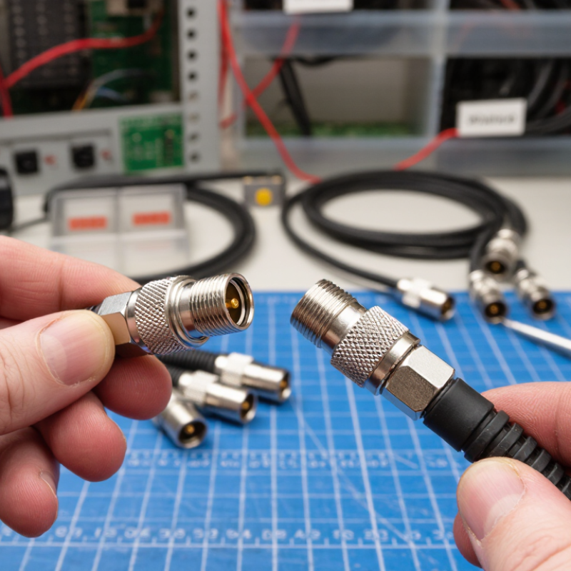
A TNC cable assembly can look right and still fail at the equipment port. Match the cable plug to the port jack. A standard plug usually has a protruding center contact; a jack usually has a recessed contact. Catalog labels can be inconsistent, so check drawings and inspect the actual interface. MIL-STD-348B provides dimensional interface data for RF connectors, helping verify that mating parts fit correctly.
TNC connectors use threaded coupling. Confirm that both ends are standard-polarity or both are reverse-polarity; their center-contact genders differ. Match impedance as well: 50-ohm TNC assemblies are common, while 75-ohm versions also exist. Industry technical specifications often list standard TNC designs near an 11 GHz upper frequency limit, but cable and termination ratings vary. Use the rating of the lowest-rated component. A detail worth rechecking: “TNC” alone does not confirm impedance or frequency performance.
Tips: Before ordering, record each port’s connector type, polarity, impedance, and frequency range. Compare these details against the assembly drawing and datasheet—not just a product title. If the port is hard to reach, take a clear close-up photo.
Select Coaxial Cable by Attenuation, Shielding, and Minimum Bend Radius
How to Choose a TNC Cable Assembly in 2026
Select Coaxial Cable by Attenuation, Shielding, and Minimum Bend Radius
Start with the operating frequency and total cable length. Attenuation rises with frequency, and even a short assembly can lose useful signal when the cable is too lossy. Compare manufacturer data at your actual frequency, not just a broad “low loss” label. Include connector transitions in the signal path; they add small, real losses. Check the assembly’s specified frequency range and measurement conditions.
Shielding matters near switching equipment, radios, or dense cable runs. Look for construction details such as foil and braid coverage, plus how the shield terminates at each TNC connector. A high coverage figure alone does not guarantee a quiet installation. It is easy to miss. Where interference is consequential, review shielding test data or ask how it was measured.
Bend radius can decide whether a cable survives installation. Check the minimum static radius for fixed routing and the dynamic radius if the cable will move. Never force a tight turn against a panel edge; leave room near the connector, where repeated strain can damage the cable. I still find routing plans look generous on paper. A physical mock-up often reveals the awkward corner. After assembly, inspect the route and verify continuity and insertion loss against the project requirements.
How to Choose a TNC Cable Assembly in 2026 - Select Coaxial Cable by Attenuation, Shielding, and Minimum Bend Radius
| Cable type | Nominal impedance | Typical outside diameter | Typical attenuation at 100 MHz | Typical attenuation at 1 GHz | Typical attenuation at 3 GHz | Shield construction and indicative screening | Minimum static bend radius* | Typical use |
| RG-174/U | 50 Ω | About 2.8 mm | About 25 dB/100 m | About 80 dB/100 m | About 140 dB/100 m | Single braid; moderate screening, commonly around 60–80 dB depending on frequency and test method | About 14 mm (5 × cable diameter) | Compact, flexible, short runs where space and weight matter |
| RG-58/U | 50 Ω | About 5.0 mm | About 11 dB/100 m | About 40 dB/100 m | About 75 dB/100 m | Single braided shield; moderate screening, commonly around 60–80 dB depending on construction and test method | About 25 mm (5 × cable diameter) | General-purpose 50 Ω connections and moderate-length runs |
| RG-223/U | 50 Ω | About 5.4 mm | About 13 dB/100 m | About 43 dB/100 m | About 78 dB/100 m | Double braided shield; generally higher screening than single-braid cable, often around 80–100 dB under specified test conditions | About 27 mm (5 × cable diameter) | Applications needing stronger shielding and a durable cable build |
| RG-400/U | 50 Ω | About 4.9 mm | About 14 dB/100 m | About 46 dB/100 m | About 82 dB/100 m | Double braided shield; typically high screening, with actual effectiveness varying by frequency and cable construction | About 25 mm (5 × cable diameter) | Higher-temperature or demanding environments; commonly uses a fluoropolymer dielectric and jacket |
| RG-8X | 50 Ω | About 6.1 mm | About 7 dB/100 m | About 23 dB/100 m | About 43 dB/100 m | Shield construction varies; foil plus braid versions can provide high screening, subject to the specified test method | About 31 mm (5 × cable diameter) | Lower-loss option for longer runs when a larger cable is acceptable |
Selection notes: Attenuation figures are representative cable-level values in dB per 100 m; actual values vary with manufacturer, cable construction, temperature, and frequency. Shielding figures are indicative only and depend on frequency and measurement method. A 50 Ω TNC assembly should use a cable and connectors with matching impedance. Confirm the assembly’s rated frequency, power handling, shielding performance, and bend limits against the specific datasheets.
*The listed bend radius is an approximate static installation guideline, not a universal specification. Follow the cable manufacturer’s minimum bend radius; dynamic or repeated-flexing applications generally require a larger radius.
Compare Assembly Data for VSWR, Return Loss, and Insertion Loss
How to Choose a TNC Cable Assembly in 2026
Compare assembly data across the full operating band, not just at one frequency. Ask for a calibrated test report showing VSWR, return loss, and insertion loss at stated frequency points. IEC 61169-17:2022 specifies TNC connector requirements, but the finished cable assembly still needs its own measured results. Check the cable length, connector configuration, and test conditions. A report without these details is hard to compare.
VSWR and return loss describe the same mismatch from different angles. For example, a measured VSWR of 1.25:1 corresponds to about 19.1 dB return loss. This is an illustration, not a universal acceptance limit. Insertion loss shows how much signal the assembly loses; record it across the sweep, especially near the highest frequency you use. NIST Technical Note 1297 explains how measurement uncertainty should be evaluated and reported. Ask whether the test setup’s uncertainty could change a pass/fail result. Small print matters. A clean-looking graph can hide a sharp loss rise near the band edge, and I would not choose from a single headline value alone.
Verify Power, Temperature, Sealing, and Test Requirements Before Ordering
How to Choose a TNC Cable Assembly in 2026
Before ordering, define operating frequency, peak power, and duty cycle. A TNC assembly’s power capacity is not one universal figure; it changes with frequency, cable type, ambient temperature, and connector condition. Ask for the supplier’s power derating curve and the test frequency behind it. Specify the required insertion loss and VSWR, too. IEC 61169-17 describes TNC connector interfaces, but the assembled cable still needs verification against your application. Small details matter: a short cable near a warm enclosure may need more thermal margin than its length suggests.
Temperature and sealing need equal attention. State the actual operating and storage ranges, plus exposure to rapid temperature changes, moisture, or cleaning fluids. IEC 60068-2-14 provides a standardized temperature-change test method. For outdoor use, specify the required IP rating for the complete, correctly mated assembly—not just the connector. IEC 60529 defines IP67 as dust-tight protection and temporary immersion at 1 metre for 30 minutes under specified test conditions. A threaded coupling alone does not guarantee that result.
Tips: Request RF sweep results at your operating frequencies, continuity checks, and a documented environmental test plan. Confirm whether sealing was tested with the cable routed and connector torqued as installed. This is often missed. Review the test limits before approval; an unclear requirement can produce a technically sound assembly that still fails in the field.
Temperature is only one selection check. These are illustrative typical jacket-material ranges, not guaranteed ratings for a finished TNC cable assembly. Formulations and component limits vary; confirm the complete assembly’s datasheet. Before ordering, verify RF power at the operating frequency and conditions, temperature limits, required sealing/IP rating, and test criteria with the supplier.